

Screw Visualisation
I was asked to produce a photorealistic render of a new performance screw by my friends at KAL Group. So, I thought I’d put together a bit of an overview of its construction.
I started out with the technical diagram of the screw (in the form of a PDF). I used that to create a bunch of viewport images that I could use for reference when building the geometry. One thing I had to do initially however, was correct the aspect ratio of the diagram – which was slightly stretched. I was able to build a very accurate model from the diagram alone, however it wasn’t obvious how the underside of the screw head was constructed.
When I received the physical item, it differed slightly to the technical diagram. I updated the model to take into account the differences. Also, being an uber-nerd, I used a Veho USB Microscope to get a good close up of the screw. If you haven’t seen a USB microscope, I recommend getting hold of one. They’re quite inexpensive (around £40) and come in really handy for stuff like this.
Creating the body of the screw was relatively straightforard, however matching the thread to the technical diagram took a fair bit of trial and error. To compound things, this particular screw had saw teeth towards the front, along with a semi-circular rebate cut out of the tip. In the end, I lofted the thread onto a helix spline. I then applied a series of loft adjustments to vary the width and size of the thread along the length of the screw. Finally, I applied a couple of boolean operations to cut the teeth and semi-circle. It was kind of like replicating the real-life sequence used to create the screw in the factory, with tools (boolean objects) applied in sequence to remove bits of geometry.
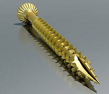
For the final image, the client requested that I extend the thread further up the screw – so the final version differs again from the physical screw:
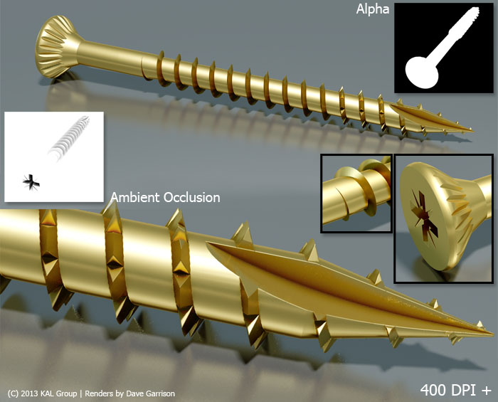
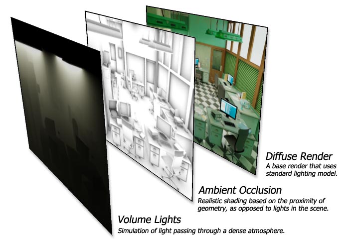
Finally, rendering. There are only two materials in the scene, both are metallic. The final images were rendered at 4000 x 4000 pixels – more than enough for most uses. A fair amount of manual clean-up work was required for the boolean areas (the sharp bit at the front!) both in the geometry and final renders. The final images were a composite of diffuse render, with an ambient occlusion layer to enhance the thread. I also added an alpha channel so the screw could accurately be extracted from the background.
Screw Visualisation
- Categories →
- 3D Visualisation
- Illustration (CAD)
Portfolio
-

The F2 – Target Tekkers

-

Football Clash All Stars
-

Car Photographer Tools
-

Dr Popper Video Game
-

Unity Image Renderer
-

Murder Detective 3 – Prototype
-
Steel Rope Visualisation
-

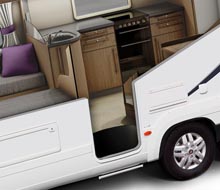
Motorhome in Modern Architecture
-
Screw Visualisation
-

Motorhome on Beach
-

Motorhome in Surf
-

Motorhome Abstract
-
Vehicle Cut-out Illustration
-
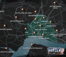
MD2 Game Map
-
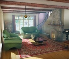
Traditional Home
-

The Dockyard CGI
-
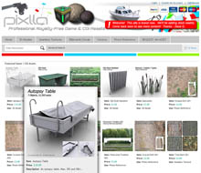
Pixlla.com | Website
-
MD2 Promo Video
-
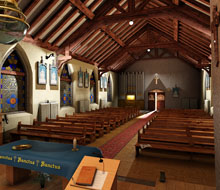
Inside Lynton Church
-
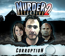
Murder Detective 2: Corruption
-
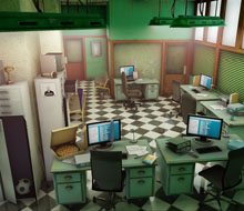
The Police Headquarters
-
Lynton Church
-
Phil’s House Boat
-

Tournay Software Logo
-
Hampton River
-

Mijnlieff Prototype
-
The Golden Chinese Restaurant
-
The Study
-
The Tattoo Parlour
-
Interrogation Room
-

BattleBallz Chaos
-
Need for Speed Carbon GBA
-

Need for Speed Most Wanted GBA
-

Need for Speed Underground 2 GBA
-

Need for Speed Underground 2 DS
-

Need for Speed Underground GBA
-

Need for Speed Porsche Unleashed GBA
-

TOP GUN FIRESTORM GBA
-

TOP GUN FIRESTORM GBC
-

E.T. The Extra Terrestrial GBC
-

Ultimate Fighting Championship GBC
-

Army Men Air Combat GBC
-

Men in Black 2
-

Sensible World of Soccer ’96/’97 PC
-

Offensive | PC
-

Jungle Strike Amiga
-

Dennis | Amiga
-
Taz-Mania
-

Speedy Gonzales Game Boy